Designing the board.


For this week assigment, I wanted to play a bit with servo and attiny, I decided to do a small and simple circuit that let a potentiometer control the position of a servo motor, To do so I first went and see on the arduino website the schematic circuit for the Knob code exemple. this will be the "template" on wich I will built my circuit.


We can see here that it is a really simple circuit, we read the value of our 10k resistor via an analog pin on our microcontroller and uses a pulse with modulation to write and change the servo position depending on the read value. Seems easy enouph, let's start doing stuff!
Again, I decided to used Eagle to design my circuit, the program is just so fun and intuitive, it is really an amazing design tool so let's start by creating a new schematic inside our software. Here are all the components I will add inside my design:

  • Atitiny44
  • 10k potentiometer
  • isp headers
  • usb mini socket
  • 4 pos screw terminal


  • as you can see, this will be a really simple circuit and uses only a few components exept the 10k potentiometer and the screw terminal that will be used to connect my servo motor, we find the attiny44 that will run the code, the isp headers to program the atitiny44 and an usb socket for wich I will bring power to my board. Thats it! Easy peasy!

    I found the eagle library for my potentiometer on Snapeda this really useful website very often ease my life by having free downloadable component lbr for Eagle and other design software. Just search the component using it's digikey Part number and see if there is any results.


    All the other components were already in my fab lbr so I was good to go, once every component import into my shem, I link them using the net command. here is the basic circuit and the final schem.


    I also uses the name and label command to link some component without having to use the net command, to do so just give two pins the same name and they will be link together. here are the result.


    Now that the schematic is done, we can create our board, to do so, just press the generate board button, you will then see all your component link by a yellow line, you now have to move your component and place them like you wish them to be placed on your final pcb.


    Now you can make your trace by selecting the route buttons, or do like I do and setup your DRC so you can use the autorouter tool to make your trace automatic. Here are my DRC parameters for this board.


    Now select your autorouter tool, make sure your set the autoroute at only one layer and let the magic happen!


    The board is done and ready to go into our CAM program!

    Preping the Gcode and Milling the board


    As usual I will use Flatcam to prepare my Gcode, but before even opening the software I must convert my board into an gerber file for my traces and into an excellon file for my holes. To do so, just open the CAM processor tool into EAGLE and load the gerber and excellon job.


    Then just process the job and youre ready to import into flatcam!

    Into Flatcam, go into file and open a gerber file, the file you are looking for is a .cmp and .drd


    You can now go into the selected tab for each job (gerber and excellon) to setup your parameters, I work with a 0.0054" engraving bit for my traces, and to make sure my soldering job will not be hell to do, I make 7 passes and combine them into one job.


    Then you can go and select the newly created .iso file and go back into the selected tab, here are my settings :


    Same process for the excellon, I use a 0.315" drill, so here are my parameters:


    Now that our Gcode are made, let's mill the board, as usual you need to home your machine a make sure your Z0, is perfect, you can do this by using a multimeter, also make sure you use good double side tape so that your copper plate is level correctly on your machine bed.


    Just lauch your Gcode a see the result, you can sand the board with a really not heavy sandpaper (I use 400) and clean it with a cleaning paper. here are the results.


    Alrright these are pretty good results, i'm happy with my board so let's go solder!

    Soldering the board


    As usually, soldering the board is a piece of cake when youre in the right state of mind, just be calm and keep your nerves downn, always start by the hardest component like the microcontroller and the usb socket:


    Then go with the easiest part, easy peasy, lets program it to put it to the test!


    Programming the board


    To program the board I once again used the arduino IDE, so as usual first thing I had to do was to declare my variable.


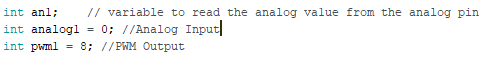
    int an1;    // variable to read the analog va1ue from the analog pin
               int analog1 = 0; //Analog Input
               int pwm1 = 8; //PWM Output


    Then in my setup I define the type of my pins:


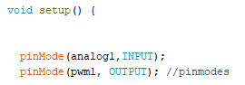
    pinMode(analog1,INPUT);
         pinMode(pwm1, OUTPUT); 


    This is easy, we read the analog1 pin of the potentiometer so we set it as a input, while we write the result of the analog pin onto the pwm1 pin and send it to our servo so it is an output!

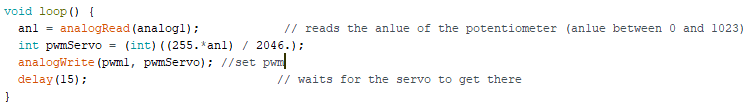
    Next the loop, this is where it gets fun:


    void loop() {
              an1 = analogRead(analog1);            // reads the an1ue of the potentiometer (an1ue between 0 and 1023)
              int pwmServo = (int)((255.*an1) / 2046.); // convert the analog value to a pwm value
              analogWrite(pwm1, pwmServo); //set pwm
              delay(15);                           // waits for the servo to get there
              }
    
    As we know Pulse with Modulation is a digital signal that simulate an analog one, the way it works is that the signal is still digital so it is composed of 1 or 0, HIGH or LOW, This on-off pattern can simulate voltages in between full on (5 Volts) and off (0 Volts) by changing the portion of the time the signal spends on versus the time that the signal spends off. The duration of "on time" is called the pulse width. To get varying analog values, you change, or modulate, that pulse width. Here is an exemple of me reading the pwm signal of my board using an osilloscope:


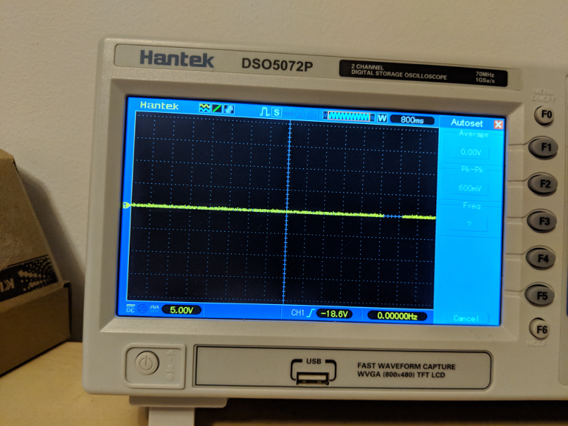
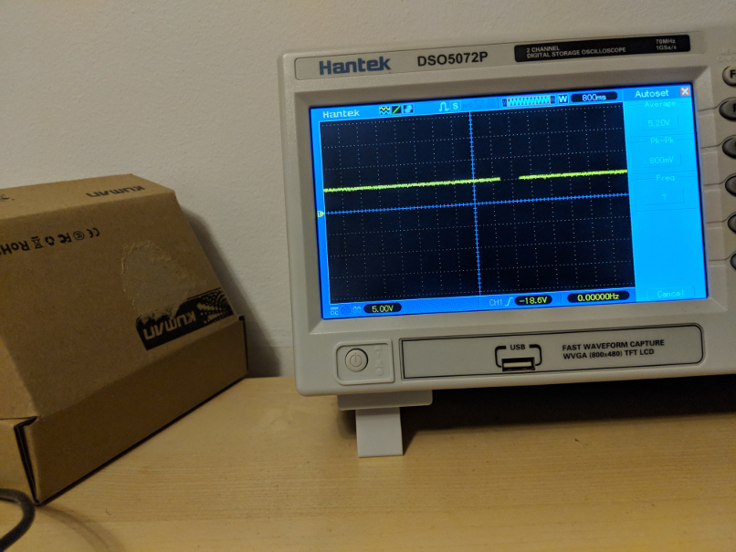
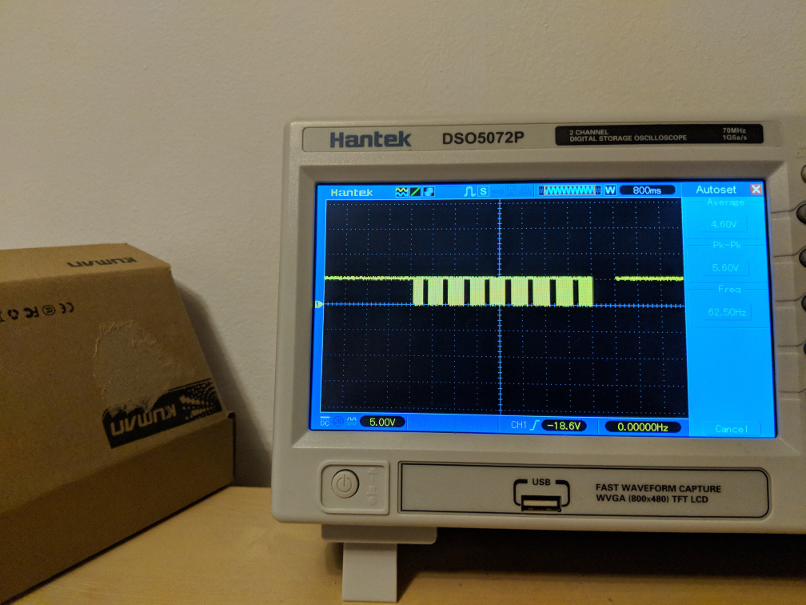
    We can see in the first image that my signal is a 0V this is when my potentiometer is at full capacity, it represent a LOW signal (0 / 255) on the second picture, we see a stable 5v is HIGH (255 / 255), finally we have an image of a square modulation, this is my potentiometer a mid capacity, the signal is converted into HIGH and LOWS and the time between each cycle will set our voltage.

    One thing to consider is that an analog signal is set between 0 and 1023 while a PWM signal is set between 0 and 255, thats why I wrote the line
    int pwmServo = (int)((255.*an1) / 2046.)
    this line take my analog signal, and map it into an pwm treshold. lets uplaud the code and see if it works! 
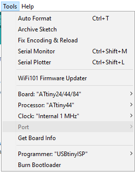
To uplaud the code we do as usual, make sure your programmer is set as usbtiny and that you have selected the correct board.


    once the code is uplaud you can test your board!


    It works! good job, I had a lot of fun this week, here are my files!